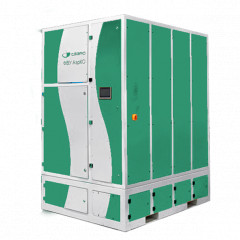
AerCO TURBO 10 000 FVU

 In stock
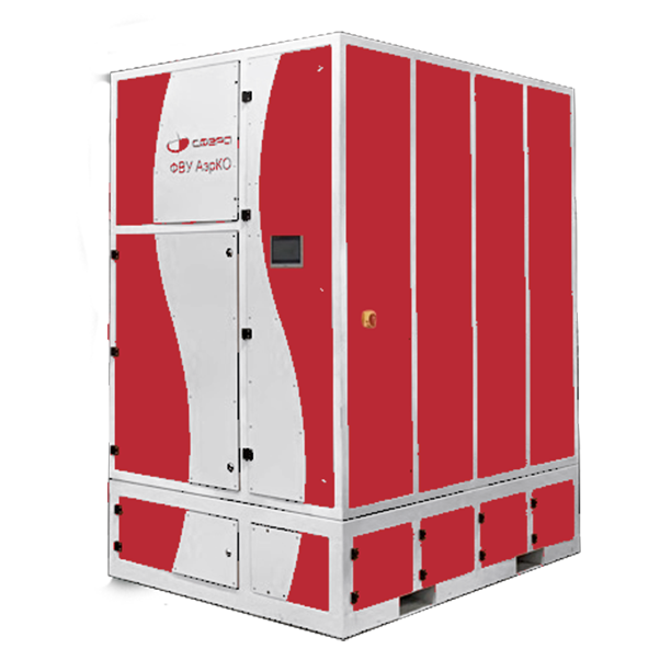
The AerCO TURBO 10 000 FVU performs two-stage air filtration in production where laser and plasma cutting, welding and abrasive processing of metals are used.
- Description
- Main elements
*– the real FVU flow rate is given, without taking connected external duct lines into account.
Air purification in the AerCO TURBO FVU takes place as the air moves through first- and second-stage filters. Because the operation of process equipment that is a source of polluted air (laser and plasma cutting machines, welding and abrasive equipment) may produce sparks – particles of metal heated to a high temperature – the first-stage filter of the FVU is an aerodynamic chamber that, besides filtration, acts as a spark arrestor.
The AerCO TURBO FVU has an original hopper design: each cyclone works with its own independent hopper. This prevents air flows from crossing between the cyclones, which increases the overall efficiency.
Thanks to the integrated design solutions, the aerodynamic chamber provides a purification efficiency of up to 95% for particles larger than 5 µm, which significantly exceeds the values typical of cyclone filters.
In addition, the aerodynamic chamber solves the task of pre-filtering oil smoke that arises, for example, during laser cutting of metal sheets covered with an oil film.
For high-quality air purification from particles smaller than 5 µm, the AerCO TURBO FVU uses second-stage filters – fine-filtration cartridge filters.
Contamination of the cartridge filters that occurs while the FVU is running is removed by blowing them with compressed air. The cleaned air is discharged by the FVU through the outlet opening in the top wall of the FVU body.
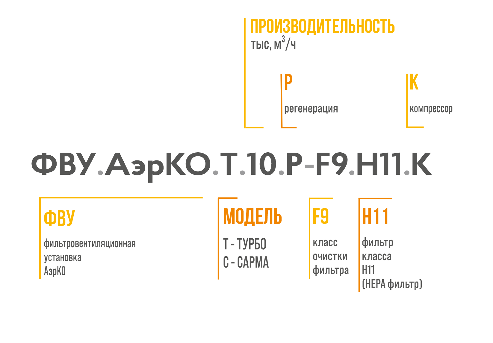
Technical specifications:
- Overall dimensions (L×W×H) – 2360x1702x2591 mm.
- Weight – up to 1525 kg.
- Number of filters (cyclone/cartridge) – 4/6.
- Fan drive power – 11 kW.
- Flow rate – 8000-10000 m³/h*
- Cartridge filter regeneration system – present.
- ⌀ Inlet nozzle diameter – 315 mm.
- Type of regeneration system – pneumatic.
*– the real FVU flow rate is given, without taking connected external duct lines into account.
Main elements:
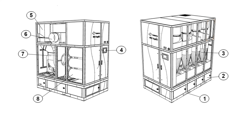
The numbers in the figure indicate:
- Forklift slots
- Dust collection hoppers
- Cyclone filters
- Touch control panel
- Air duct
- Inlet nozzle (for a pipe of 315 mm diameter)
- Radial fan
- Cartridge filters